
Objective
Equipment & Details
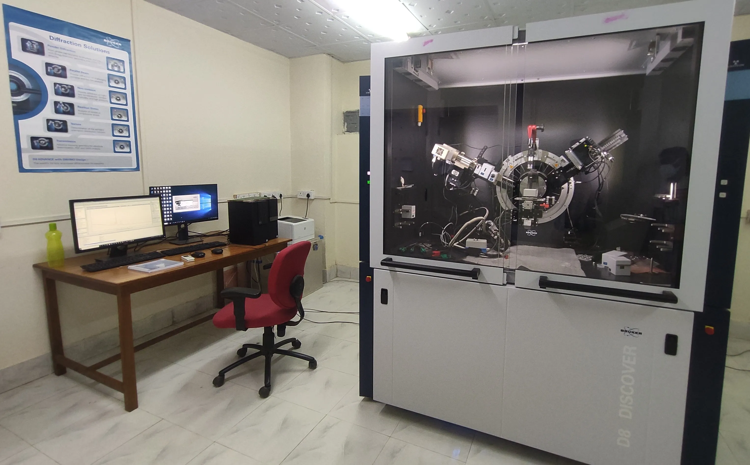
2D-X-Ray Diffraction Lab
Model: D8- DISCOVER
Specification
TWIST-TUBE:
Easy switch between point and line focus
Available anodes: Cr, Cu, Mo, Ag
Max. Power and filament: up to 3 kW depending on anode material (0,4 x 16 mm² )
Patent: EP 1 923 900 B1
IµS Micro Focus Source:
Power load: up to 50 W, single-phase power
MONTEL and MONTEL Plus optics combining parallel and focusing mirrors.
Beam sizes down to 180 x 180 µm².
Maximum integrated flux 8 x 10? cps at mirror exit.
Beam divergence down to 0,5 mrad
Turbo X-Ray Source (TXS):
Line focus, 0.3x3 mm²
Focal brightness of 6 kW/mm²
Anode materials: Cu, Co, Cr, Mo
Max. voltage 50 kV, max. power depending on anode material: Cr 3.2 kW, Cu/Mo 5.4 kW, Co 2,8 kW
Pre-Aligned Tungsten filament
TRIO Optics: Software push-button switch between:
Motorized Divergence Slit (Bragg-Brentano)
High Intensity Ka1,2 Parallel Beam
High Resolution Ka1 Parallel Beam
Patents: US10429326, US6665372, US7983389
High-Resolution Monochromators:
Ge (220) and Ge (004) reflections in symmetric and asymmetric geometry
2-bounce and 4-bounce (Bartels type) Monochromators
Alignment-free mounting through SNAP.LOCK technology
D8 Goniometer:
Two-circle goniometer with independent stepper motors and optical encoders
UMC Stages:
Family of sample stages
x, y for sample translation of up to +/- 150 mm
z-Drive with travel of up to 50 mm
Phi drive with infinite rotation
Max. Psi inclination up to 55°
Max. weight (at center position): 50 kg
Centric Eulerian Cradle (CEC):
Five degrees of freedom sample stage:
x, y for sample translation of +/-40 mm
z-Drive for height alignment
Phi drive with 360° rotation
Psi drive and angular range from -11° to 98°
Max. weight load: 1 kg
Various stage attachment available.
Pathfinder Plus Optics:
Software push-button switch between:
Motorized Slit
2-bounce Ge Analyser
Automated absorber integrated
LYNXEYE XE-T:
Energy Resolution: < 380 eV @ 8 KeV
Detection Modes: 0D,1D, 2D
Wavelengths: Cr, Co, Cu, Mo and Ag
Patents: EP1647840, EP1510811, US20200033275
EIGER2:
The latest generation multi-mode (0D/1D/2D) detector based on the Hybrid Photon Counting technology, developed by Dectris Ltd.
Non-ambient:
Temperature: Ranging from ~12 K up to ~2500 K
Pressure: 10-? mbar up to 100 bar
Humidity: 5% to 95% RH
Sample Details
- Samples must not contain volatile, corrosive, toxic and radioactive substances and/or these substances must not be evolved during the test.
- The sample should not contain radioactive ,toxic and explosive materials.
- Care must be taken to create a flat upper surface and to achieve a random distribution of lattice orientations.
- Smaller sample dimensions are preferred. Sample with thickness 5mm to 10 mm length/width/diameter are ideal.
Utility and Working Principle
X-ray diffraction analysis (XRD) is a
technique used in materials science to determine the crystallographic
structure of a material. XRD works by irradiating a material with
incident X-rays and then measuring the intensities and scattering angles
of the X-rays that leave the material. A primary use of XRD analysis is
the identification of materials based on their diffraction pattern. As
well as phase identification, XRD also yields information on how the
actual structure deviates from the ideal one, owing to internal stresses
and defects. Crystals are regular arrays of atoms, whilst X-rays can be
considered as waves of electromagnetic radiation. Crystal atoms scatter
incident X-rays, primarily through interaction with the atoms'
electrons. This phenomenon is known as elastic scattering; the electron
is known as the scatterer. A regular array of scatterers produces a
regular array of spherical waves. In the majority of directions, these
waves cancel each other out through destructive interference, however,
they add constructively in a few specific directions, as determined by
Bragg's law:
Where d is the spacing between diffracting planes is the incident angle, n is an integer, and ? is the beam wavelength. The specific directions appear as spots on the diffraction pattern called reflections. Consequently, X-ray diffraction patterns result from electromagnetic waves impinging on a regular array of scatterers. X-rays are used to produce the diffraction pattern because their wavelength, ?, is often the same order of magnitude as the spacing, d, between the crystal planes (1-100 angstroms).
Applications:
- Phase Identification and quantification, structure determination and refinement, Micro strain and crystallite size analysis.
- X-Ray reflectometry, Grazing Incidence Diffraction (GID), High-resolution XRD, crystal orientation analysis
- Residual Stress analysis, Texture and pole figures, micro X-ray Diffraction, Wide Angle X-ray Scattering (WAXS),
- Total scattering analysis: Bragg Diffraction, Pair-Distribution Function (PDF), Small Angle X-Ray Scattering (SAXS)